Figure 4.

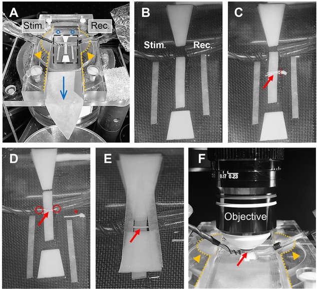
Optic nerve preparation in setup for electrophysiology and imaging. (A) Photograph of the recording chamber with stimulation (Stim.) and recording (Rec.) electrode. Orange arrow heads highlight the modification to the Haas top unit of the chamber; i.e., the inside edges (dotted lines) are milled down in a 45° angle to create better access for electrodes and objective, see also (F). Blue circles and arrow indicate location of ACSF inflow into the chamber and direction of flow, respectively. Black rectangle outlines the region magnified in (B) showing the arrangement of filter papers around the electrodes. (C) The optic nerves (red arrow) are placed on the central filter paper strips (two layers) with the chiasm facing the recording electrode. One nerve is carefully cut from the chiasm (dashed red line) and moved towards the electrodes. (D) Depicted is how the nerve is positioned on the filter paper strips between the electrodes with each nerve end inserted into the suction electrodes (red circles). The other nerve is placed on the side as backup (red asterisk). (E) Organization of the remaining filter papers above and below the electrodes before (F) placing the objective above the nerve (red arrow) by dipping into the created ACSF pool. Orange arrows heads indicate the modification (milling) of the inside edges of the chamber (dotted lines).
