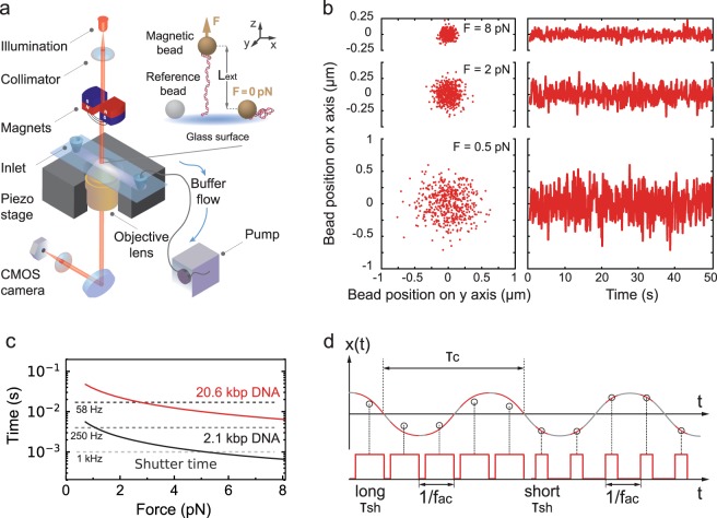
Figure 1.
Magnetic tweezers assay and experimental characteristics. (a) A magnetic tweezers setup consists of an inverted microscope, a flow chamber and a pair of permanent magnets (represented here vertically aligned, as used in the experiments). In the flow chamber, the nucleic acid molecules are attached at one end to a magnetic bead and at the other end to the flow chamber bottom glass coverslip top surface. The magnets are placed above the flow cell and decreasing their distance to the magnetic beads increases the force applied to the tether. A collimated light source located above the magnets illuminates the flow chamber through the magnets gap. The light is collected by an oil immersion objective underneath the flow chamber and the field of view is imaged onto a complementary metal-oxide-semiconductor (CMOS) camera (Material and Methods). (b) Lateral displacements of a MyOne bead tethered to the 20.6 kbp DNA construct at three different forces (8 pN, 2 pN and 0.5 pN). (c) The characteristic timescale (tc,x) of the fluctuations along the x-axis of a MyOne magnetic bead tethered by either a 20.6 kbp (red) or a 2.1 kbp (black) DNA construct as a function of the applied force (Material and Methods, Equation (2)). The dashed grey lines indicate the shutter time (τsh) of the camera for different acquisition frequencies (58 Hz, 250 Hz and 1 kHz). (d) Illustration of the effect of long and short τsh on the estimation of the position of a system with a defined characteristic time τc at constant fac.

