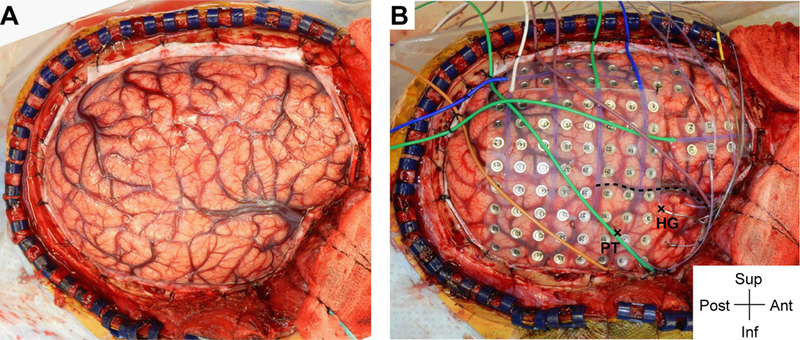
FIG. 1.

Intraoperative photograph demonstrating exposure and intracranial electrode placement. A right frontotemporoparietal craniotomy (A) allowed proper exposure for placement of grid, strip, and depth electrodes (B), including the HG depth electrode. The sylvian fissure is marked with a dashed line. The HG depth electrode and the PT depth electrode are marked with X symbols anteriorly and posteriorly, respectively, at their entry points at the cortical surface. Ant = anterior; inf = inferior; post = posterior; sup = superior. Figure is available in color online only.
