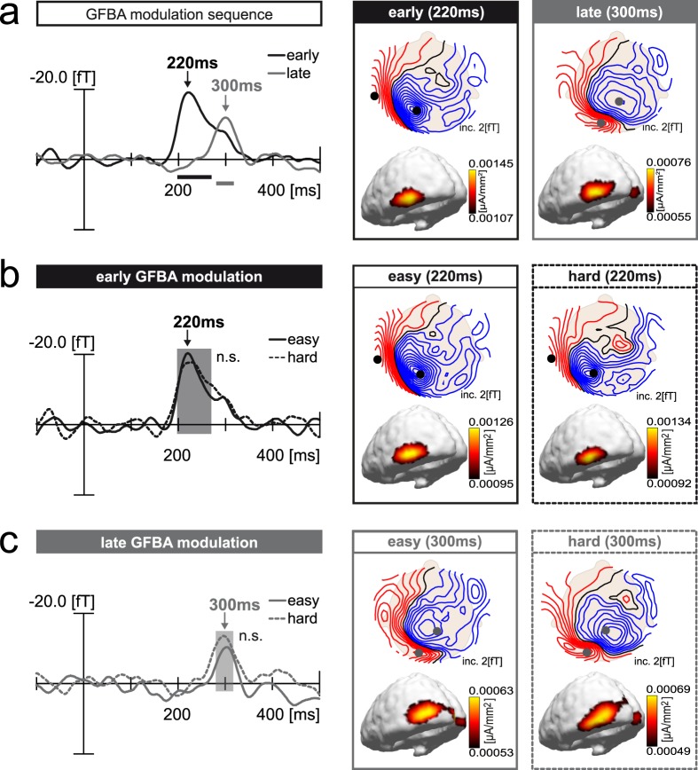
Figure 3.
GFBA effects (M-NM difference) of Experiment 1. (a) Overall GFBA modulation sequence (match minus non-match difference, averaged across easy/hard conditions). Magnetic field distribution maps (top view, upper row) and corresponding 3D current source density distribution maps (lateral/back view, lower row) at time points of early and late effect maxima are shown on the right. ERMF waveforms of the early (black trace) and late (grey trace) GFBA modulation on the left display the signal of sensors located at the respective field distribution maxima (sensor sites indicated by black and grey dots in the field distribution maps, signal collapsed over influx (blue field lines) and efflux (red field lines, polarity inverted prior averaging) maximum). (b) Early GFBA modulation. The waveforms show the early GFBA effect of the easy (black solid) and hard (black dashed) condition. Respective field distribution maps and corresponding current source density distributions are displayed on the right. (c) Late GFBA modulation. The waveforms show the late GFBA effect of the easy (grey solid) and hard (grey dashed) condition with corresponding magnetic field maps and current source densities displayed on the right. Sensor sites for the early and late effect (black and grey dots in the field distribution maps) were always chosen at locations of the overall effect maxima (easy/hard average, see (a)). Horizontal black and grey bars (a) as well as black and grey rectangles (b,c) indicate time windows of significant match vs. non-match comparisons as determined for the overall GFBA effects (p < 0.05, corrected for multiple comparisons, as described in Methods).

