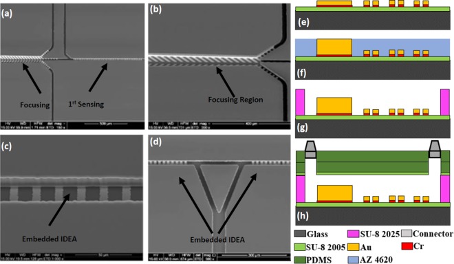
Figure 8.
SEM of the sensor: (a) Focusing and 1st Sensing region, (b) Magnified view of the focusing region. The excess waste will leave through the channels on two sides while the bacteria stay in the center and enter the sensing region, (c) Magnified view of the IDE arrays for sensing region embedded in the microchannel, (d) IDE arrays for 2nd and 3rd Sensing regions. The triangle part is used to split the fluid during antibodies collection for 2nd and 3rd sensing regions to reduce cross-contamination. Cross-sectional view demonstrating multiple layers of the sensor: (e) Electrode traces on top of the SU8 and glass slide, (f) Electroplating to increase the height of the focusing wall, (g) SU8 microchannel, (h) PDMS and fluidic connectors as seal.

