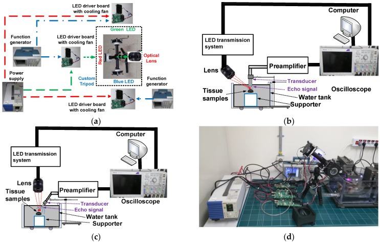
Figure 6.
(a) Layout of the multiwavelength LED–US instrument with target samples, (b) experimental setup when the lens was placed diagonally on the left and the transducer was placed vertically on the right, (c) experimental setup when the lens was placed vertically on the left and the transducer was placed diagonally on the right, and (d) multiwavelength LED–US experimental instrumentation.

