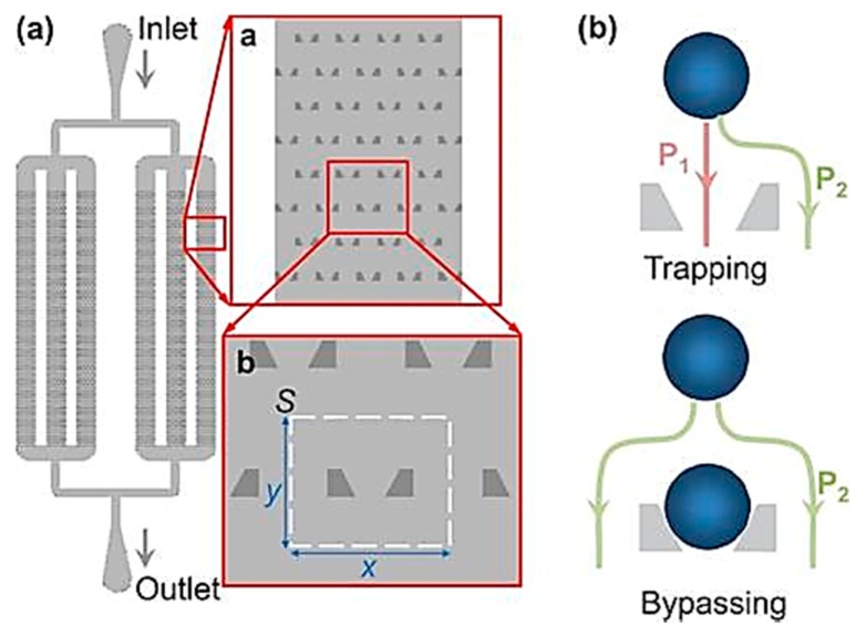
Figure 10.
Schematic representation of the microfluidic microsphere-trap array. (a) Layout (top view): Microfluidic channels with hydrodynamic trap arrays. The channels are connected by a common inlet and a common outlet. Liquid solution carrying the microspheres flows from the inlet and through the chamber; (b) Trapping mechanism. Reproduced from [68] with the permission of AIP Publishing.

