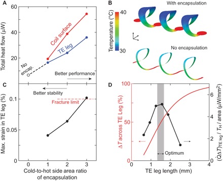
Fig 2. Considerations in thermal engineering to optimize choices of design parameters.

(A) The total heat flow across the silicon thermoelectric (TE) leg (blue) increases as the width of the cold side of the encapsulated polymer layer is increased. The overall heat dissipation through surface convection (red) increases the heat flow. (B) Simulated temperature profiles by FEA that compare the encapsulated case (the ratio of the area of the cold to the hot side is 2) to the non-encapsulated case with identical geometry. The encapsulation lowers the temperature at the cold side of the leg. (C) Maximum strain in the thermoelectric leg as a function of the ratio of the area of the cold to the hot side. Increasing the area of the cold side, while desirable for improved performance, compromises the mechanical stability. An area ratio of 2 balances heat exchange capability and mechanical stability. (D) With an area ratio of 2, the leg length is selected to maximize (right axis, normalized to TH and area), which is the impedance matching condition. The corresponding fractional temperature drop across the leg is shown on the left axis. All findings presented here are the results of modeling of 3 × 1 coil structures (three leg pairs) with a hot-side thermal bath of 40°C and the entire surface subject to convective heat dissipation due to ambient air at 21°C.
