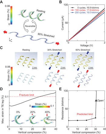
Fig 3. Mechanical deformability and durability of 3D thermoelectric harvesters.

(A) Simulated distributions of strain in the silicon thermoelectric leg before and after uniaxial stretching in the plane by 60%. The results indicate reductions in strain upon stretching, as expected based on the compressive buckling process used to form the 3D structures. (B) Results of experimental durability tests that involve multiple cycles of 60% uniaxial stretch and release on a 3 × 1 coil structure (strain rate ≈ 0.01 s−1). The data indicate only a small increase in the electrical resistance. (C) Optical images (top row) and simulated structures (bottom row) upon in-plane stretching. (D) Simulated values of the maximum local strain in the thermoelectric leg induced by vertical compression. A maximum compression of 26% is possible before reaching the fracture strain of the silicon, the limiting factor for this system. The inset shows the deformed structure upon compression, including a strain distribution map of the silicon leg. The maximum strain occurs near the hot side, indicated as the fracture point (see also fig. S8). (E) Experimental measurements of the device resistance upon vertical compression. The onset of an increase in resistance occurs near the limit predicted by simulation. At a compression of 40%, the device shows open-circuit behavior due to fracture of the silicon.
