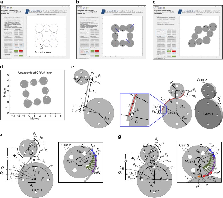
Fig. 5.
Software design tool enabled by the compliant rolling-contact joint (CRJ) modeling theory. a Cam locations, connections, and radii are specified by the user in the tool’s design window. b Loads are defined. c The design is simulated. d Its unassembled layer geometry is given. e Geometric parameters that define a single CRJ layer. Parameters that define the strap loads imparted on CRJ cams for general f tension and g compression scenarios

