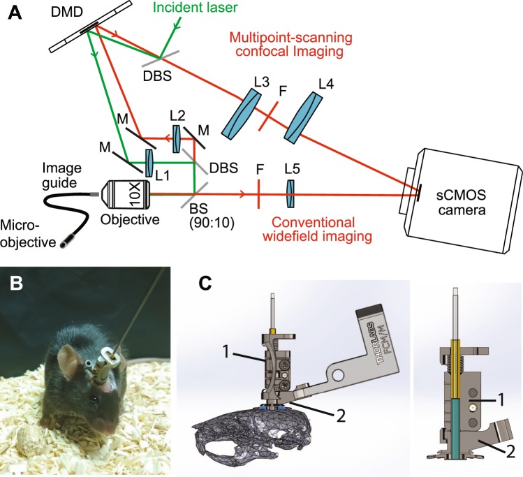
Figure 2.
Optical setup. (A) A custom-made microscope comprising one illumination path (green) and two detection paths (red) is coupled to the animal brain using an image guide attached to a micro-objective. The central element of the fiberscope setup is a DMD, which is used to create a matrix of illumination and detection pinholes. The optical setup is fully described in the methods. Lenses L3 and L4 are off-axis to partly straighten up the multipoint-scanning confocal image at the camera. DBS: dichroic beam splitter. M: mirror. BS(90:10): beam splitter with 90% reflection and 10% transmission. F: filter. (B) Picture of an unrestrained (freely behaving) mouse in its cage with the fiberscope probe fixed on the skull. (C) Fixation of the image guide (ferrule shown in yellow) and GRIN lens (ferrule shown in cyan) to the skull. The image guide is attached to the GRIN lens using a connection device (piece 1). The GRIN lens is fixed to the skull using a head plate (piece 2) that is positioned using a micromanipulator.

