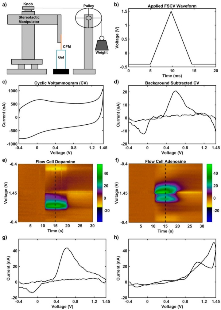
Figure 1.
Experimental setup and fast scan cyclic voltammetry methodology. (a) Schematic of the mechanism used to produce motion of the carbon fiber microelectrode through agar solution without generating electromagnetic interference. (b) Example triangular voltage waveform applied to carbon fiber microelectrode vs. the Ag-AgCl reference electrode. (c) Example current obtained at all voltage points during application of triangle waveform (cyclic voltammogram) in (b). The current generated includes both capacitive and faradaic components. (d) Example cyclic voltammogram obtained via background subtraction during a transient dopamine concentration change, which emphasizes faradaic changes such as the oxidation near 0.6 V and the reduction near −0.2 V. (e–h) Known signals for dopamine and adenosine obtained via measurement in a benchtop flow cell (different than the setup in Figure 1A) using the methodology described by Shon et al. [54]. Briefly, a flow cell passes buffer solution by the electrode continuously with transient boluses of electrochemical in order to produce a phasic signal. High concentrations (1 μM dopamine and 5 μM adenosine) were passed by the carbon fiber microelectrode in pure buffer to produce large, idealistic—low noise—signals to emphasize the characteristic faradaic components (e) Dopamine signal with characteristic oxidation at 0.6 V and reduction at −0.2 V. (g) Characteristic cyclic voltammogram of dopamine signal from (e) (collected at dotted vertical line). (f) Adenosine signal with characteristic primary oxidation at 1.4 V and secondary oxidation at 1.0 V. (h) Characteristic cyclic voltammogram of adenosine signal from (f) (collected at dotted vertical line).

