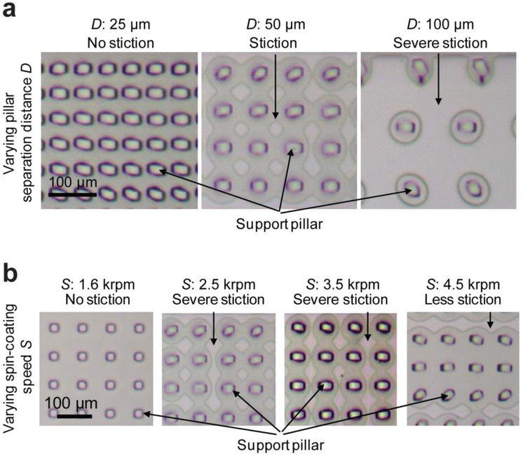
Figure 4.
Bright field images illustrating deformation and stiction of thin PDMS membranes to the bottom of vacuum channels when V-PAM was implemented. (a) shows representative images for support pillar arrays with the same width W but different separation distances D (D = 25, 50, 100 µm) as indicated. (b) shows representative images for thin PDMS membranes generated with different spin-coating speeds S as indicated. D: 50 µm. In all cases, P: 12.5 psi, V: 12.5 psi, and W: 25 µm.

