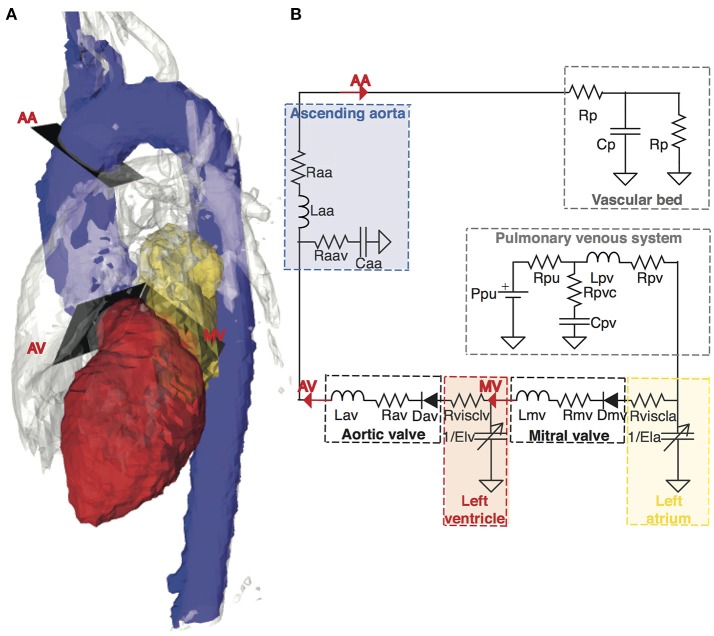
Figure 1.
Anatomical configuration and equivalent lumped parameter model of the cardiovascular system. (A) Anatomy of a representative subject shown as a 4D PC-MR angiogram at peak systole, including segmentations of anatomical regions of interest for the model: the left atrium (yellow), the left ventricle (red), and the aorta (blue). The analysis planes used for extracting subject-specific input flows for the model are located at the mitral valve (MV), aortic valve (AV), and ascending aorta (AA). (B) A schematic representation of the lumped parameter model. The building blocks corresponding to the different anatomical compartments are highlighted in dashed lines and color-coded according to the anatomical representation in (A) Descriptions of the parameters in the model can be found in Supplementary Table S1.

