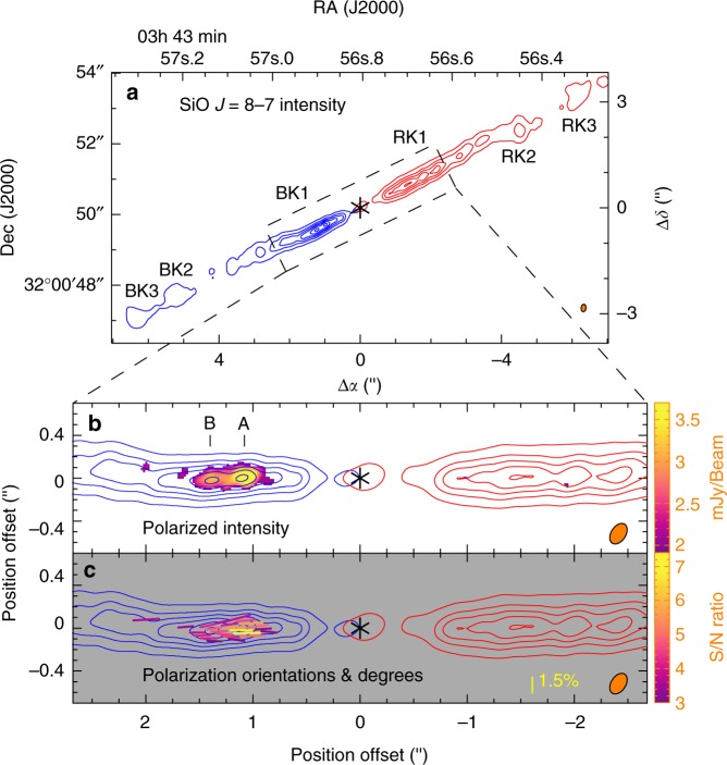
Fig. 2.
a Polarization results towards the inner part of the HH 211 jet in SiO J = 8–7. The resolution is 0ʺ.21 × 0ʺ.14, as shown with the elliptical beams in the bottom right corners. Asterisks mark the source position. In a, knots BK1, BK2, BK3, RK1, RK2, and RK3 are the SiO knots identified before11, 19. Subknots A and B, where polarized emission is detected, are the two subknots in knot BK1 resolved in this work. In b, c, the image of the jet is rotated by 26.6° clockwise to be aligned with the x-axis. The blueshifted component (blue contours) is obtained by averaging the emission from −22 to 8 km s−1, and the redshifted component (red contours) from 11 to 42 km s−1. The contours start from 30σ with a step of 60σ, where σ~ 0.64 mJy per beam, which is the noise level of polarized emission. b The color image shows the polarized intensity >3σ detection. c Line segments show the polarization orientations (E vectors), with their length indicating the polarization degree. They are color coded according to their S/N ratio in polarized intensity

