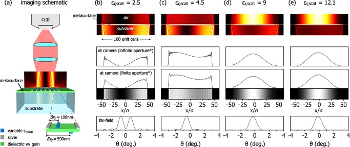
Figure 4.
Intensity patterns due to leakage of the 1st order dark mode for a system with N = 100 unit cells, for different outcoupling strengths. The scatterers have a 30 nm × 60 nm rectangular cross section, fixed positions as shown and the outcoupling strength is tuned via their permittivity εr,scat, which is set to 2.5 in (b) (weak), 4.5 in (c) (moderate), 9 in (d) (strong), and 12.1 (e) (very strong). The top row shows |Ez|2 at the vicinity of the metasurface, which is located horizontally in the middle of the panel. The far-field image seen with a camera is shown in the two middle rows, for ideally infinite aperture and realistically finite aperture of NA = 0.32 (shown as density plot as well). *Aperture here refers to the numerical aperture of the imaging lens, as opposed to the aperture size of the radiating metasurface. The bottom row shows the far-field angular distribution.

