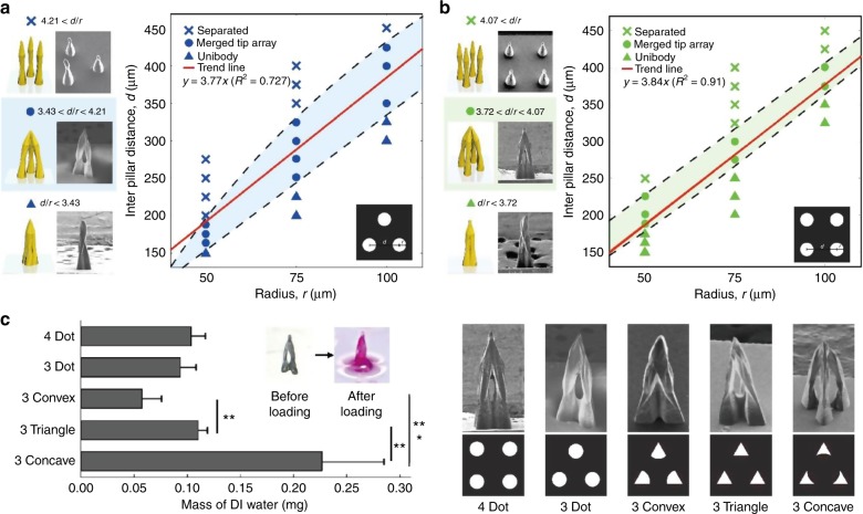
Fig. 2. Design Rules for Tip Merging.
Structural phase diagram for merged-tip microneedle fabrication without integrating the micropillars into a single body and separating the micropillars (▲: uni-body, ●: merged tip, ×: separated); SEM images and illustration of elasto-capillarity-driven patterning for each phase with the respective number of micropillars demonstrated above the graph. In addition, the range of the distance-to-radius ratio corresponding to each phase is indicated under the images, while the equation of the design rule for constructing MTMs is on the graph. a Three circular patterns (scale bar: 200 μm) and b four circular patterns (scale bar: 150 μm). c Mass of DI water to be trapped in the cavity of a single MTM, which is constructed using three concave-, three triangle-, three convex-shaped patterns, three circular, and four circular, respectively. Error bars represent standard deviations (n = 5). Significance levels were set at **P < 0.01, ***P < 0.001. The design of the template mask corresponding to the respective shape of pattern (top) and SEM images of MTMs manufactured using the film mask for each type of pattern (bottom) are demonstrated. The scale bar indicates 200 μm

