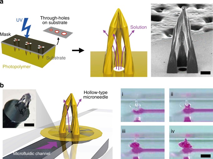
Fig. 5. Hollow Type MTM Fabrication and Loading.
a Schematic diagram of the photolithographic fabrication process and liquid delivery system of the hollow MTM with an SEM image of a three triangular pillar array design. The scale bar indicates 200 μm. b Illustration of the solution delivery through the microfluidic channel-based pores on the through-hole membrane into the cavity of the MTM and the optical microscopy image of the system. Sequential photographs of the rhodamine B solution flow through the pore of the through-hole PEG-DA membrane by time (steps i–iv). The scale bar indicates 2000 μm

