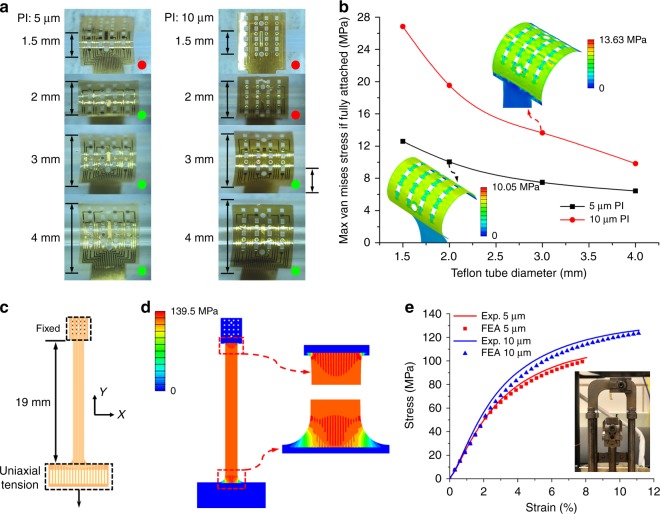
Fig. 8. Flexibility and mechanical property of the microelectrode arrays with an overall thickness of 5 or 10 μm.
a Attachment experiments of PI microelectrode arrays on Teflon tubes with different diameters of 1.5, 2, 3, and 4 mm. The red and green dots represent poor and good contact, respectively. b The simulated maximal stresses of the arrays with different thicknesses when fully attached to the Teflon tubes with the same diameters. The insets show the stress distribution of the fully attached 5 μm PI on a 2 mm tube and 10 μm PI on a 3 mm tube, respectively. c The diagram of the uniaxial tensile test of the microelectrode array with one side fixed and the other side under uniaxial tension. d Stress distribution of the PI microelectrode array with a thickness of 10 μm at the fracture critical state. e Experimental and FEA results of strain vs. stress curves of 5- and 10-μm-thick arrays. The inset shows the broken specimen in the DMA

