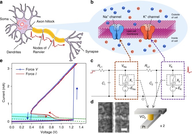
Fig. 1.
Circuit diagram of a biomimetic active memristor neuron and active memristor device characteristics. a Schematic structure of a biological neuron, showing that an action potential is fired near the axon hillock (under sufficient input stimulus) and propagates along the cell axon towards the output synapses. b Mechanism of voltage-gated Na+ and K+ ion flows across the cell membrane that accounts for the action potential generation and repetition across the nodes of Ranvier (myelin-sheath gaps). A similar mechanism exists in neurons that lack a myelin sheath. c Basic circuit topology of a two-channel active memristor neuron to emulate the neuronal dynamics in (b). A voltage-gated Na+ (K+) channel is emulated by a negatively (positively) d.c. biased active memristor device, which is closely coupled with a local membrane capacitor C1 (C2) and a series load resistor RL1 (RL2). d Schematic structure and a scanning electron micrograph of a typical VO2 active memristor nano-crossbar device (X1 or X2 in (c)). Scale bar: 100 nm. e Typical two-terminal quasi d.c. voltage-controlled (force V) and current-controlled (force I) I–V characteristics of a VO2 active memristor device. A wide hysteresis loop exists in the voltage-controlled mode due to the Mott transitions (blue arrows). The same Mott transitions are manifested by an “S” shaped negative differential resistance (NDR) regime (highlighted by cyan color) with a much narrower hysteresis (red arrows) in the current-controlled mode. In its resting state, the resistor load line for memristor X1 (or X2) intersects with its I–V loci outside the NDR regime (green dotted line). An input current or voltage stimulus can shift the load line into the NDR regime (green dashed line) and elicit an action potential generation (spiking)

