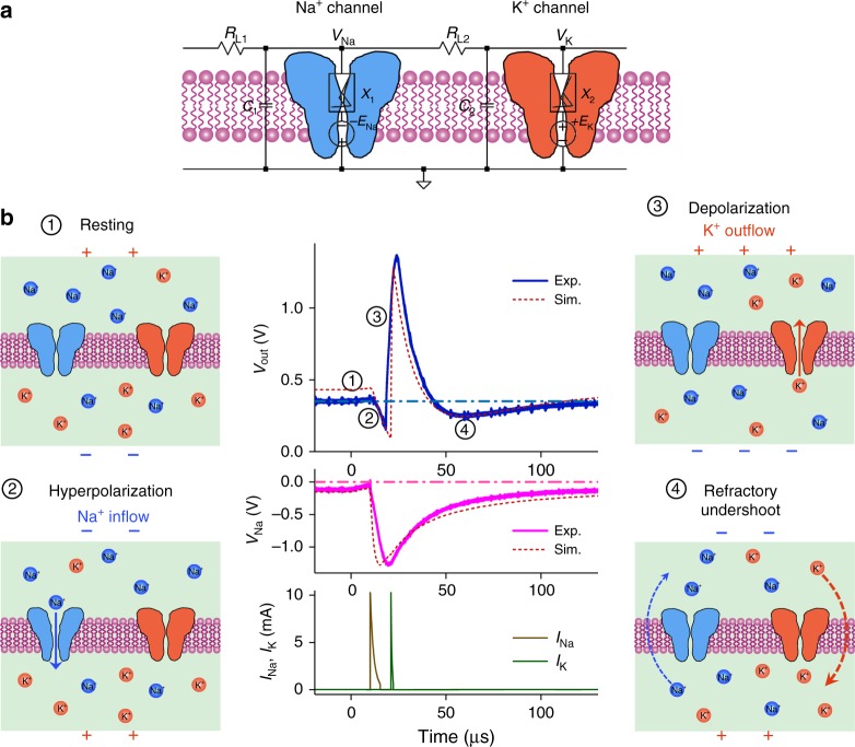
Fig. 2.
Action potential generation in a VO2 active memristor neuron. a Circuit diagram of a VO2 memristor neuron, consisting of two resistively coupled Pearson-Anson relaxation oscillators (RL1, C1, X1 and RL2, C2, X2, respectively). The negatively-biased memristor X1 acts as the voltage-gated Na+ channel, and the positively-biased memristor X2 acts as the voltage-gated K+ channel. Capacitors C1 and C2 are the corresponding membrane capacitances. b Basic steps in action potential (spike) generation of a VO2 neuron. (1) Resting state, in which both the Na+ and K+ channels are closed. A resting potential of 0.2–0.3 V is produced by a membrane leakage current flowing through the VO2 devices in their insulating state. (2) Hyperpolarization caused by the activation of the Na+ channel, which drives the membrane potential toward negative direction. (3) Depolarization caused by the activation of the K+ channel, which drives the membrane potential toward positive direction. (4) Refractory (undershoot), during which the neuron is recovering and does not respond to another stimulus. The central plots are experimental and simulated action potentials (top), the Na+ channel membrane potential VNa (middle), and simulated Na+ and K+ channel currents (bottom)

