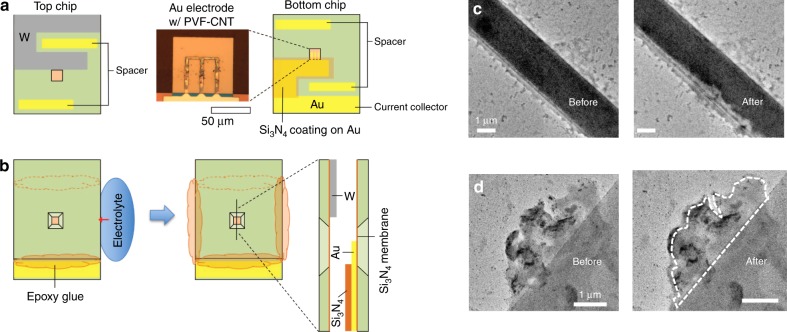
Fig. 4.
In situ TEM investigation of the redox-active metallopolymer under electrochemical modulation. a Schematic illustration of the top and bottom chips for the liquid cell. The optical micrograph image shows the PVF film deposited on the Au electrode patterned on the Si3N4 membrane window. b Chip assembly process. The two chips were overlapped and the two sides of the perimeter sealed with epoxy glue. The electrolyte was contacted with the side opening and injected into the cell via the capillary effect. A magnified cross-sectional view at the windows is illustrated. Detailed fabrication procedures for each component are given elsewhere34, with the polymer electrodeposition process described in Methods. c In situ TEM micrograph of PVF layer on top of gold chip. A solution of 20 mM NaClO4 was introduced and a CV @ 0.1 V/s was applied to the two-electrode system; a clear expansion of the PVF film can be seen following ion insertion (Supplementary Movie 1). d Swelling and contrast change of a PVF film under electrochemical modulation in the presence of 10 mM (NH4)2Cr2O7 (Supplementary Movie 3). See SI for all associated movies and cyclic voltammograms for Fig. 1c, d

