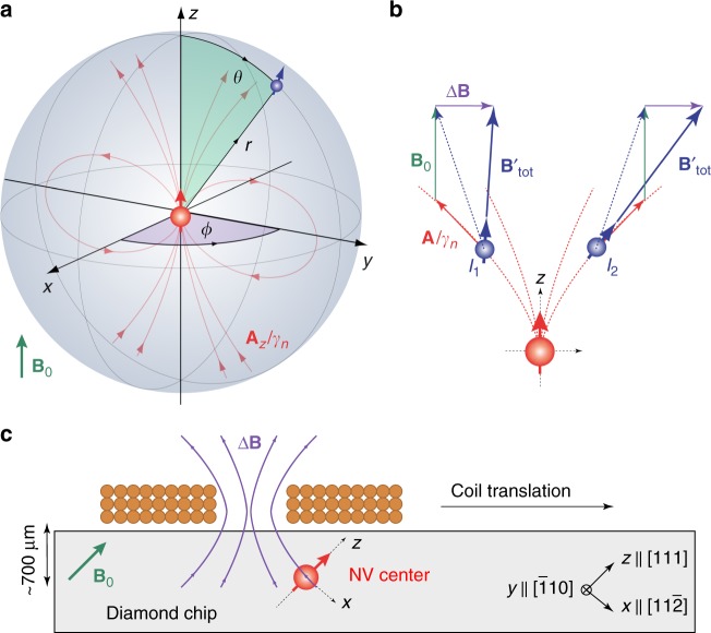
Fig. 1.
Coordinate systems for spins and magnetic fields. a Reference frame of the central nitrogen-vacancy (NV) sensor spin (red) with a nuclear spin (blue) located at the three-dimensional position r = (r, θ, ϕ). The quantization axis of the NV center defines the z-axis. The hyperfine field of the NV spin (red field lines) provides the magnetic field gradient for imaging. b Sketch of two nuclear spins I1 and I2 experiencing the same hyperfine interaction (red) [Eq. (2)]. Application of a transverse field ΔB (purple) reduces (I1) or increases (I2) the total magnetic field (blue) experienced by the nuclear spins depending on the ϕ angle, allowing us to discriminate the nuclear locations. B0 is the static external field (green). c Geometry of the experimental setup in the laboratory frame of reference. A small solenoid on top of the diamond chip provides a rapidly switchable magnetic field ΔB. To change the vector orientation of ΔB, we translate the coil over the diamond

