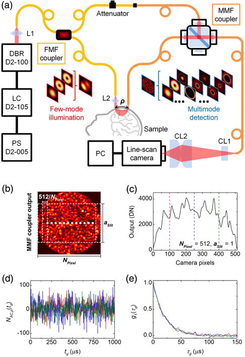
Fig. 2.

(a) Schematic of multimode iDWS system based on an M-Z interferometer built from two fiber couplers. The first SMF-28 fiber coupler supports the first six vectorial modes (HE11 × 2, TE01, HE21 × 2, and TM01) at 852 nm. In the reference arm, the SMF-28 output fiber connects to the MMF coupler via an APC mating sleeve, with a variable attenuator to avoid camera saturation. The splitting ratio of the MMF coupler is 95/5 (T/R). The core and cladding diameters of the step-index MMF are 105 μm and 125 μm, respectively, and the NA is 0.15. The light source is an 852 nm DBR (distributed Bragg reflector) laser with <1 MHz linewidth and >180 mW output power, modulated by a 500 mA LC (laser controller, D2-105-500, Vescent Photonics) with a PS (power supply, D2-005, Vescent Photonics). L1 and L2: spherical lens; CL1 and CL2: cylindrical lens; PC: personal computer. (b) The intensity pattern at the MMF coupler output is detected by a 512 pixel CMOS array. Pixels are binned horizontally to form NPixel binned pixels consisting of 512/NPixel pixels each, with fractional heights of aSlit. (c) Instantaneous power measured by the pixel array with NPixel = 512 and aSlit = 1. (d) Segments of heterodyne signal time courses (∼1 ms) extracted from the three pixels marked by vertical dashed lines in (c). (e) Normalized field autocorrelations calculated from full-time courses (∼100 ms) of the three heterodyne signals in (d).
