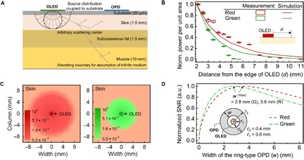
Fig. 2. Design considerations for low-power OPO sensors.

(A) Schematic of the proposed optical skin model used in this study. (B) Measured and simulated normalized power measured at a distance measured from the edge of an OLED. Box and line charts represent experimental and simulation results, respectively. (C) Top view of the simulated optical power distribution at the surface of a skin. The light from each OLED is optically coupled to the skin and scatters from various organelle back to the top surface. The radius of each OLED (r0) is set at 0.4 mm. (D) Calculated normalized signal-to-noise ratio (SNR) versus the width (W) of the concentric, ring-type OPD for light originating from a circular OLED with r0 = 0.4 mm. The inner radius (r1) of the ring-type OPD is set at r0 + 0.2 mm (= 0.6 mm) in consideration of fabrication margin. The SNR values obtained here are with fH(r=r1) and l0 of 0.01 W/m2 and 2.3 mm for red and 0.01 W/m2 and 1.8 mm for green OLEDs. For details on estimation of SNR, refer to section S3.
