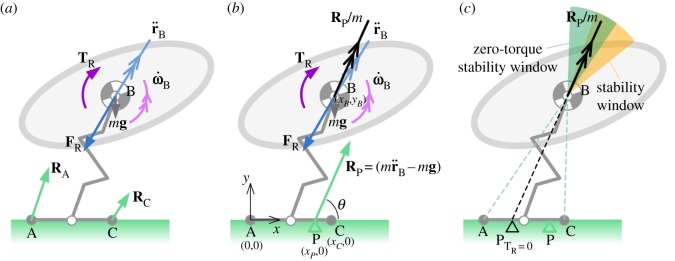
Figure 4.
Diagram depicting the planar jumping system with body, extensible leg and foot with ground contact points at the rear and front toe (A and C, grey circles). Revolute joints are located at the body–leg and leg–foot interface (open circles). Body linear and angular acceleration are shown as vectors and . (a,b) The inertial force and torque are shown as vectors FR and TR. Ground reaction forces at the front and rear toe are depicted as RA and RC, respectively, and the net ground reaction force, RP, is equal to the vector sum of the body inertial and gravitational forces, and gives rise to the net acceleration Rp/m. (b) The coordinate system is depicted for calculating the location of the CoP, P, shown as a green triangle. The acceleration angle, θ, is shown as the angle between the horizontal (x) axis and the ground reaction force vector. (c) The coloured sectors are stability windows within which the acceleration vector must point to avoid tipping. PTR=0 shows the hypothetical location of the CoP for zero inertial torque (TR = 0). The green sector is the case with zero angular acceleration (zero torque), the yellow is the case with positive, nose-up angular acceleration, and the overlapping region of these two sectors is illustrated as the dark green sector. The edges of the green sector align with the front and rear of the foot, as shown by the dotted lines. A similar (but less intuitive) graphical definition of the yellow stability window is that its edges would align with the front and rear of the foot if the foot were displaced backwards by a distance equal to the distance between PTR=0 and P; this has been omitted from the diagram for clarity.

