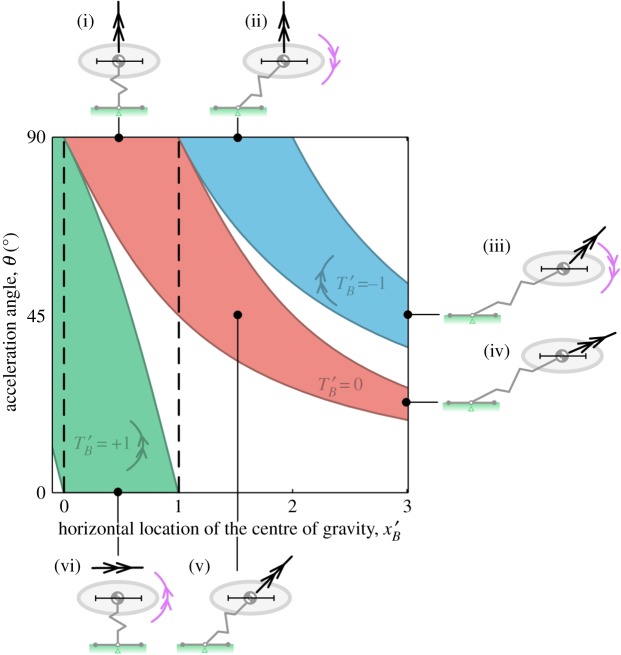
Figure 5.
Stability map showing bounds on the centre of gravity fore–aft location to prevent tipping. The horizontal axis represents the horizontal location of the centre of gravity, and black dashed lines mark the position of the rear toe (x'b = 0) and front toe (x'b = 1). The vertical axis represents the acceleration angle, 0° being horizontal acceleration and 90° being vertical. The three different coloured regions represent stability boundaries under different conditions of applied torque: red is no torque, blue is a nose-down torque and green is nose-up. Thumbnail images (i)–(vi) are example acceleration conditions with the corresponding stable centre of gravity ranges shown as black horizontal bars, with the centre of gravity illustrated at the centre of each bar; all of the cases shown are stable, with the CoP located at the middle of the foot.

