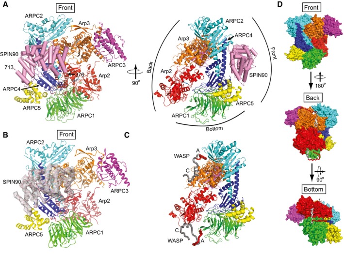
Figure 3. SPIN90 binds to the front side of Arp2/3 complex.

- Ribbon diagram of Arp2/3 complex with bound SPIN90 from the co‐complex structure. SPIN90 is shown in pink with cylindrical helices. Conventional designations of “Front”, “Back”, and “Bottom” views are indicated in right panel.
- Ribbon diagram showing front side of Arp2/3 complex and bound SPIN90 with Fo−Fc electron density map contoured at 2.1 σ calculated without phases from SPIN90 (chain M).
- Model of bovine Arp2/3 complex with bound WASP CA segments modeled based on crosslinking/mass‐spectrometry, homology modeling, x‐ray crystallography, and FRET (Padrick et al, 2011; Ti et al, 2011; Boczkowska et al, 2014; Jurgenson & Pollard, 2015; Rodnick‐Smith et al, 2016a; Luan et al, 2018). The complex is in an identical orientation to the right panel in (A).
- Surface representation of model described in (C) showing the convention for front, back, and bottom views of Arp2/3 complex.
