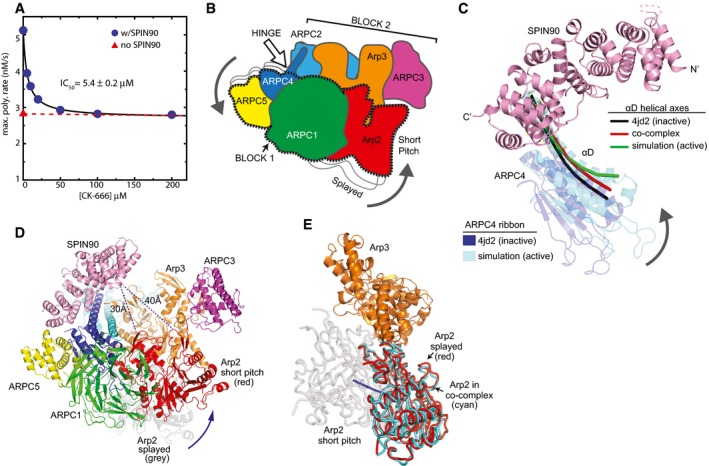
Figure 5. Binding of the SPIN90 ARM domain to the ARPC4 long helix may stimulate movement of Arp2 into or toward the short‐pitch conformation.

- Plot of maximum actin polymerization rate versus concentration of the small‐molecule Arp2/3 complex inhibitor CK‐666. Reactions contained 3 μM 15% pyrene‐labeled actin, 50 nM Bos taurus Arp2/3 complex, and the indicated concentrations of CK‐666.
- Cartoon of “rotation model” for movement of Arp2 into the short‐pitch conformation. White arrow shows the approximate position of a hinge point for the rotation.
- Structural superposition showing the proposed hinge movement in ARPC4 and the position of bound SPIN90 relative to the hinge. Residues 156–168 from ARPC4 and residues 247–260 from ARPC2 in an inactive crystal structure (4JD2) were overlaid with the same residues from the molecular dynamics (MD) short‐pitch model of Arp2/3 complex (Dalhaimer & Pollard, 2010). ARPC4 from 4JD2 (blue) and ARPC4 from the MD simulation (cyan) are shown. The helical axis of the long alpha helix (αD) in ARPC4 is shown as a black line in the 4JD2 structure and as a green line in the MD simulation structure. The red line represents the helical axis of helix αD in ARPC4 in the SPIN90‐bound co‐complex overlaid as described above. For clarity, the cartoon representation of the ARPC4 subunit in the co‐complex structure is not shown here, but is shown in Appendix Fig S10. The orientation of this panel is similar to that depicted in panels (B and D).
- Conceptual model of SPIN90‐bound Arp2/3 complex in the short‐pitch conformation. The model was made by superposing subdomains 1 and 2 of Arp3 from the co‐complex structure onto an actin subunit from a high‐resolution structure of an actin filament (3J8I; Galkin et al, 2015). Arp2 (red ribbon) was then moved into the short‐pitch position based on the filament structure. Arp2 in its original splayed position (as observed in the crystal structure) is shown in gray ribbon representation. Shortest Cα–Cα distances from SPIN90 to either subdomain 2 or subdomain 4 in Arp2 in the hypothetical short‐pitch conformation are indicated.
- Comparison of the position of Arp2 relative to Arp3 in the short‐pitch arrangement (gray Arp2), the inactive splayed arrangement (red Arp2), and the SPIN90 bound x‐ray crystal structure (cyan). The short‐pitch arrangement of Arp2‐Arp3 was modeled by overlaying subdomains 1 and 2 of Arp3 on the same subdomains in an actin subunit in the actin filament structure 3G37(Murakami et al, 2010) and then superposing Arp2 from the 4JD2 structure onto the actin subunit in the short‐pitch position. The SPIN90‐bound complex was then overlaid onto Arp3 subdomains 1 and 2 to determine the relative position of Arp2 in the SPIN90‐bound complex. Blue line shows a potential trajectory of the center of mass of Arp2 when it moves from the splayed to the short‐pitch position.
