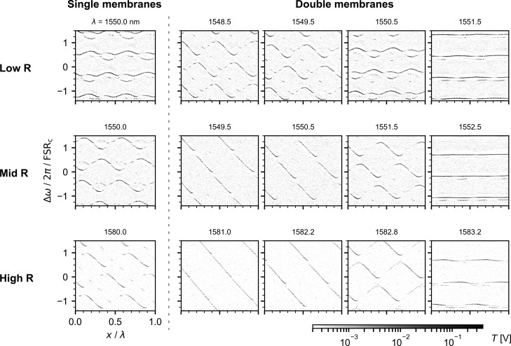
Figure 3.
Optical cavity transmission T as a function of the frequency shift Δω of the incident laser and of the displacement x of several mechanical devices placed in the middle of the cavity. Δω is normalized by the cavity free spectral range FSRc = 3.13 GHz and x by the laser wavelength λ which is indicated on top of each plot. We measured multiple devices in the middle of the cavity: on the left of the dashed line we study single-membranes and on the right double-membranes. The type of photonic crystal used in each sample is indicated on the left of the figure. Note that in order to work in a regime with a slow reflectivity change and large dip depth, the High R samples were studied at a wavelength for which Rm = 0.76.

