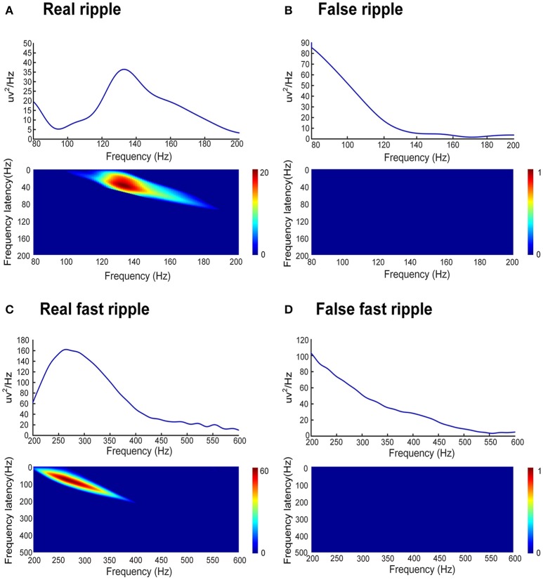
Figure 2.
Automated identification of false HFOs. (A,C) represent true and false ripples; while (B,D) show true and false FRs, respectively. The top row shows the chart of power spectral density (PSD) corresponding to period of HFO. A true HFO will show a significant power rise on the PSD (A,C), otherwise, the event should be classified as a false HFO (B,D). The second row shows the accumulated power of frequency offset power difference of the phase space reconstruction where the HFO is located. The blue color shows that the accumulated power is lower than the baseline power; we count these instances as zero and classify them as a false HFO (B,D). The red area shows the accumulated power. Instances where power is higher than the baseline power represent true HFOs (A,C).

