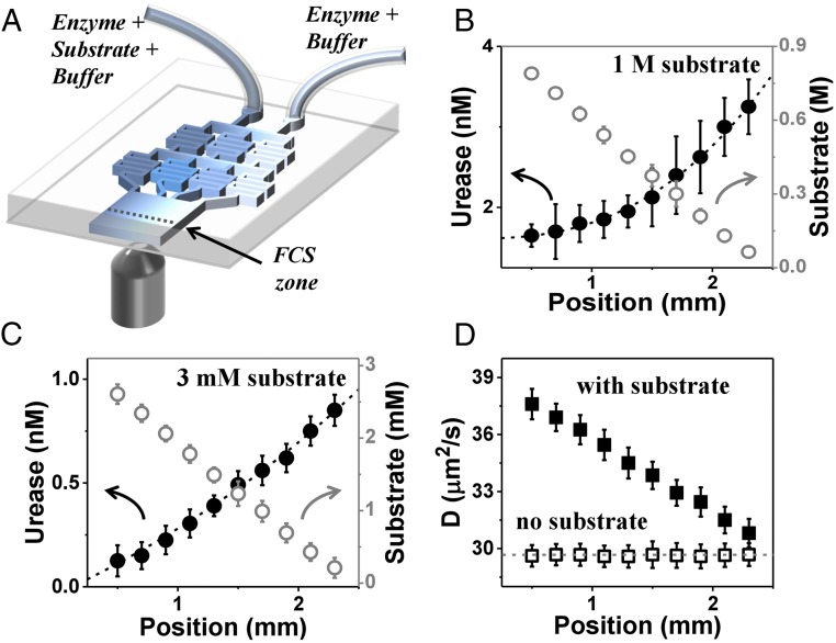
Fig. 3.
Microfluidic experiment demonstrating antichemotaxis when urease is catalytically active. (A) Schematic diagram of the microfluidic chip. The enzyme–substrate–buffer (E+S+B) enters one inlet, and the substrate-free enzyme solution in buffer (E+B) enters another, producing constant enzyme concentration across the channel but a linear gradient of its substrate. (B) Experiments at high substrate concentration: The urease concentration and substrate concentration in microfluidic chip are 5 nM and 1 M, respectively. Urease concentration extracted from FCS autocorrelation fitting and calibrated urea concentration (empty circles) are plotted against position across the channel with error bars showing SD of five repeated measurements. (C) Experiments at low substrate concentration: The urease concentration and substrate concentration at the chip inlet are 1 nM and 3 mM, respectively. (D) The enzyme diffusion coefficient (D) extracted from FCS autocorrelation fitting with a diffraction-limited spot size, plotted against position in the channel, in the presence (filled squares) and absence (open squares) of substrate, for the case of B (1 M substrate).

