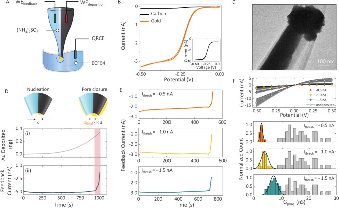
Figure 2.
Electrochemical fabrication of the nanopore–FET using real-time ionic current feedback. (A) Schematic of a bipotentiostatic configuration used to deposit and monitor gold deposition. The carbon nanoelectrode was used as a working electrode for the electrodeposition of gold (WEdeposition). To monitor the electrodeposition of gold around nanopore, another working electrode (WEfeedback) was inserted into the open barrel filled with 52 mM (NH4)2SO3 and used for real-time feedback. All potentials quoted are relative to a quasi-reference counter electrode (QRCE) placed in the plating bath filled with a 10 times diluted ECF64 gold plating solution. Potentials applied to the working electrodes were Vdeposition = −0.73 V, Vfeedback = −0.1 V. (B) To electrochemically characterize the gate electrode, cyclic voltammograms were recorded before (black) and after (orange) electrodeposition of gold, in the presence of 1 mM Ru(NH3)6Cl3 and 100 mM KCl, revealing an enhancement in the active electrode area after gold deposition. The inset confirms the formation of a carbon nanoelectrode on the tip of double-barrel nanopipettes. (C) Transmission electron microscopy micrograph showing the deposition of gold at the tip of the nanopipette and around the nanopore. d is the diameter of the nanopore. (D) Both the feedback current in the nanopore and the amount of gold deposited could be monitored in real time. (E) Ionic current feedback could be stopped at a given threshold to (F) control the pore conductance. This is shown for three threshold currents of −1.5, −1, and −0.5 nA, giving final pore conductances of 7.2 ± 1.4, 3.5 ± 1.9, and 2.0 ± 0.4 nS, respectively, as revealed by I–V characterization and histograms of nanopore conductance before and after feedback-controlled deposition of gold. The average pore conductance before gold deposition was 17.3 ± 6.4 nS (N = 90).

