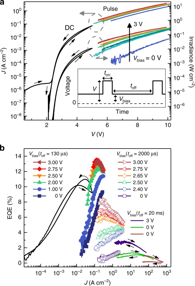
Fig. 2.

Operation under DC and pulsed drive. a Current density (left-hand axis) and irradiance (right-hand axis) versus voltage for a 200 μm diameter device operated in DC (black lines) and pulsed (colored lines) drive; small black arrows indicate the direction of the voltage sweep. Hysteresis is imperceptible in the pulsed data. The pulse width and time between pulses illustrated schematically in the inset are ton = 70 μs and toff = 2000 μs, respectively. Increasing the background bias (Vbias) significantly increases the electroluminescence intensity as indicated by the vertical black arrow. b External quantum efficiency of the same device under DC and pulsed drive (ton = 70 μs, 15 μs, and 2 μs for filled symbols, void symbols, and colored lines, respectively) with varying Vbias and toff. The highest current density trace (brown line) was achieved with a 50 μm diameter device that degraded during the reverse sweep
