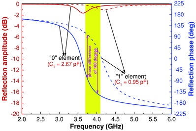
Figure 2.

Simulated reflection amplitudes and phases of the designed “0” and “1” element from 2.0 to 6.0 GHz, respectively. The yellow area presents the phase differences of the designed “0” and “1” element, ranging from 160° to 196°, when the frequency changes from 3.69 to 4.10 GHz. The two violet double arrow lines indicate the phase difference of the designed “0” element and “1” element. Obviously, the phase difference is ≈180° at 3.75 and 4.02 GHz.
