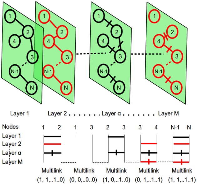
Figure 3.

At the top: the multiplex network with M layers and N nodes. At the bottom: the representation of multi-links for the different pairs of network nodes. Within each layer different nodes can be connected with a link and a specific weight. This context information is then used to detect different patterns.
