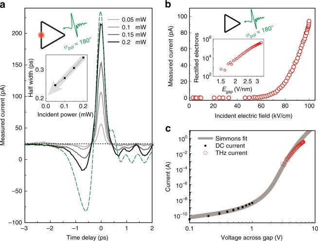
Fig. 5.
THz tunneling dynamics revealed by the optical pulses. a Measured tunneling current under the THz and optical pulses (triangle loop, side length of 500 μm, gap size of 2 nm) as a function of the time delay. Legend indicates the incident optical power. Incident polarizations are set to φpol = 180° for both pulses. The green dashed line denotes the voltage across the gap acquired from the incident THz pulse profile (corresponds to the THz pulse shown in (a)) and Eq. (1). The black dashed line crossing horizontally at 25 pA is a guide to the eye, indicating the THz current without optical pulse illumination. Inset: extracted half-width of measured currents as a function of incident optical power. Gaussian-fitting was performed for the half width extraction. The grey arrow indicates the experimentally extracted THz tunneling current pulse width. b Measured THz current under THz illumination (triangle loop, side length of 70 μm, gap size of 2 nm) as a function of THz field strengths. THz polarization is set to φpol = 180°. Inset: total rectified number of electrons per single THz pulse as a function of electric field across the gap. c Current–voltage characteristics of the ring barrier. Current data are taken only through a single side of the ring (see Methods for details). DC current and THz current data are tied to the single Simmons curve

