
Fig. 3.
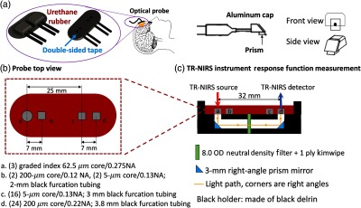
Schematic of the optical probe used for TR-NIRS measurement of tissue optical properties and DCS measurement of BFI (see main text for details). (a) The optical probe consists of prism-coupled fiber bundles embedded in urethane rubber (the prism-fiber connection is protected by an aluminum cap depicted on the right). It is secured to the forehead superior to the frontal sinuses with double-sided tape on the bottom and medical tape around the top (see Sec. 2.3.1). (b) The optical probe uses four fiberoptic bundles (labeled a, b, c, d) for TR-NIRS measurements at 0.7- and 3.2-cm SDS, and DCS measurements at 0.7- and 2.5-cm SDS. In this paper, a semi-infinite tissue model of the head was utilized for the long TR-NIRS and DCS SDS measurements (see Secs. 2.1.1, 2.2, and 4). (c) Schematic of the TR-NIRS IRF measurement (side view; see Sec. 2.3.2). As the urethane rubber mold could not be bent 90 deg to place the source (position a) and detector (position d) prisms in direct contact, right-angle prism mirrors were used instead to direct the light from source to detector.