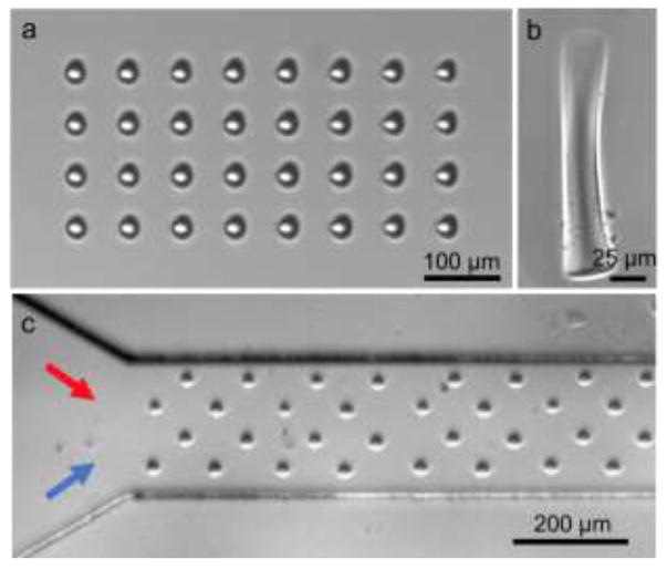
Figure 2.
Optical images of artificial cilia structures. (a) Top view of the fabricated cilia structures in the microfluidic channel. (b) Side view of a single cilium. (c) Top view of a two inlet channel with a repeated pattern of cilia structures. The red and blue arrows represent two fluids to be injected inside the channel.

