. 2018 Nov 13;7:e38922. doi: 10.7554/eLife.38922

Figure 2. X-ray structures reveal αβ-tubulins bound in a wheel-like organization around a pseudo-dimeric TOG square complex.

(A–B) 3.6 Å X-ray crystal structure of the S. kluyveri 1:2:2 sk-Alp14:αβ-tubulin:DRP reveals pseudo-dimeric head-to-tail subunits (red and orange) in a TOG square assembly consisting of four TOG domains bound to four αβ-tubulins (α-tubulin shown in cyan and β-tubulin shown in green) in a wheel-like organization. (A) Structure with DRP (yellow) bound to each αβ-tubulin. (B) Structure with DRP computationally removed. Each αβ-tubulin (α1β1) is positioned 90° rotated from its polymer-forming interface on its neighboring αβ-tubulin (α2β2). (C) Pseudo-dimeric TOG1-TOG2 subunits, shown in orange and red, respectively, form a head-to-tail TOG square (inset). Interface 1 is formed by the N-terminus of TOG2 and the TOG1-TOG2 linker binding to the C-terminus of the TOG1 domain of a second subunit, forming a 90° corner. Interface 2 is formed by the N-terminus of TOG1 binding the C-terminus of TOG2 within the same subunit in a 90° corner (Figure 2—figure supplement 1I). (D) Rainbow view of TOG1-TOG2 with N- and C-termini displayed in a blue-to-red color gradient, while the other subunit is displayed in grey. Each TOG is composed of six HEAT repeats (numbered). (E) Close-up view of interface 1. A hydrophobic zone stabilizes interface1 (yellow and highlighted by red outline) involving Leu220 (L220) and Leu217 (L217) of the TOG1 inter-HEAT 5–6 loop, Leu179 (L179) of the HEAT 6 A-helix in TOG1 (red ribbon) stabilized by linker residues (solid orange) Phe302 (F302), Leu304 (L304), and Leu305 (L305). An ionic zone guides interface 1 involving Glu219 (E219) of TOG1 inter-HEAT 5–6 loop and Glu305 (E305) of the TOG1-TOG2 linker, forming salt bridges with Lys346 (K346) and Lys347 (K347) of the TOG2 (light orange) inter-HEAT 1–2 loop and Arg390 (R390) of the TOG2 HEAT 2,3 loop, respectively. (F) Close-up view of interface 1, as in C, displaying residue conservation based on the alignment shown in Figure 2—figure supplement 2. (G) Close-up view of interface 2. A hydrophobic zone stabilizes interface 1 involving Leu477 (L477) and Leu472 (L472) of the TOG2 inter-HEAT4-5 loop with Ile43 of the TOG1 inter-HEAT1-2 loop. Ionic zone selectively guides interface 2, involving Lys39 (K39) and Ser41 (S41) of the TOG1 inter-HEAT1-2 loop and helix 1B with Arg517 (R517), Glu518 (E518), Asp521 (D521), and Glu524 (E524) of the TOG2 inter-HEAT5-6 loop and A-helix. (H) Close-up view of interface 2, as in D, displaying reside conservation based on the alignment in Figure 2—figure supplement 2.

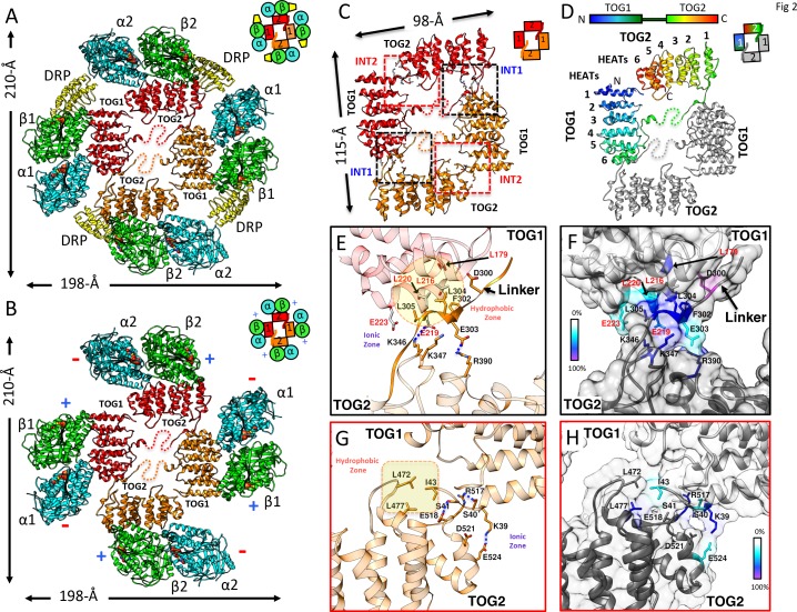
Figure 2.

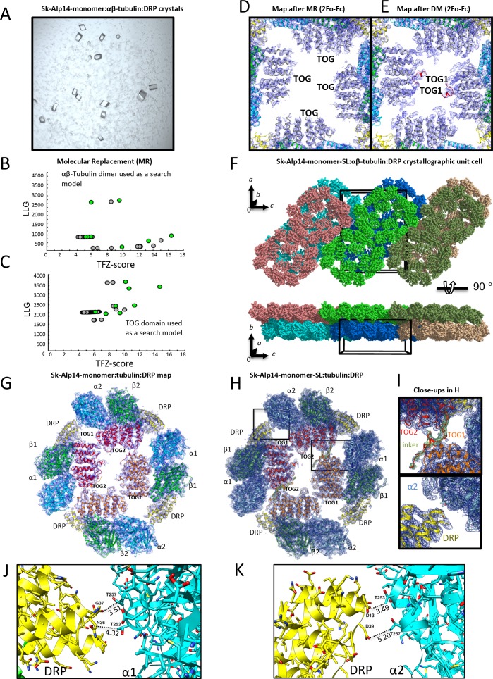
Figure 2—figure supplement 1. X-ray crystallography and structure determination of 2:4:4 Alp14-monomer:αβ-tubulin:DRP complexes.

Figure 2—figure supplement 1.

(A) Images of square crystals of 1:2:2 sk-Alp14-monomer:αβ-tubulin:DRP assemblies. (B) Molecular replacement search results for αβ-tubulin placement in the asymmetric unit. Note the distinct solution that leads to initial positioning. (C) Molecular replacement search results for the TOG domain in the asymmetric unit. (D) Initial density map of electron density for the TOG square assembly after the placement of TOG domains based on initial molecular replacement. Note the presence of only the essential features of both TOG domains. (E) Density map of the TOG square assembly after one cycle of density modification. Note the appearance of density of the linker and associating interfaces. Density maps reveal TOG1 based on its C-terminal extension and jutting C-terminal α-helix. (F) Top view along b axis of the crystallographic unit cell revealing the packing arrangement of two 2:4:4 sk-Alp14-monomer:αβ-tubulin:DRP wheel-shaped complexes in the asymmetric unit, shown in multiple colors. Bottom, a 90° rotation of the view in F, revealing the unit cell packing showing 2D sheets of wheel-shaped complexes. (G) 4.4 Å resolution 2Fo-Fc electron density contoured at 1σ of the native 2:4:4 sk-Alp14-monomer:αβ-tubulin:DRP structure. (H) 3.6 Å resolution 2Fo-Fc electron density contoured at 1 σ of the 2:4:4 sk-Alp14-SL:αβ-tubulin:DRP structure. Both G and H show the organization of the assembly and the modeled subunits. (I) Detailed close-up views of the electron-density map in H. Top, view of TOG1 (orange)-TOG2 (red) in interface 1. The linker sequence is depicted as red with green density (difference Fourier map). Bottom, detailed view of DRP (yellow) in proximity to the α-tubulin of a neighboring TOG-bound αβ-tubulin (blue). Note the lack of interactions between DRP and α-tubulin. (J) View of DRP proximity to the α-tubulin of the neighboring tubulin dimer. Note that the distances of residues are beyond 3.5 Å in most cases, showing no pattern of direct interactions. (K) View of second DRP of a non-crystallographic symmetry mate in the same orientation as shown in I.
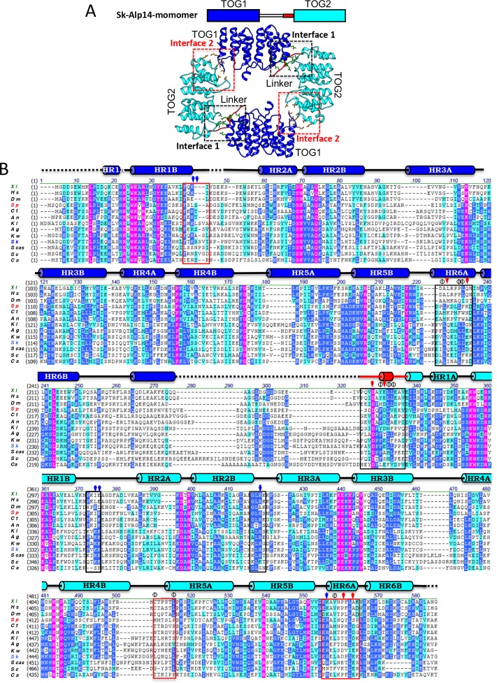
Figure 2—figure supplement 2. Sequence conservation in TOG square interfaces across each TOG1 and TOG2 domain.

Figure 2—figure supplement 2.

(A) Top scheme for Alp14, TOG1, TOG2, and linker sequence. Bottom, structure of TOG square with two TOG1 (blue) and two TOG2 (cyan) domains forming interfaces via inter-HEAT repeat elements with the TOG1-TOG2 linker sequence (red). (B) Sequence alignment of TOG1-TOG2 across multiple species with the invariant residues shown in purple, highly conserved residues in blue, weakly conserved residues in cyan, and non-conserved residues in black. The secondary structures (Cylinders, α-helices; lines, random coil; and dashed lines, disordered segments) are described above the sequences. Interfaces 1 and 2 are highlighted in black and red boxes, respectively. XI, Xenopus laveis (marked green); Hs, Homo sapiens; Dm, Drosophila melanogaster; Sp, S. pombe (marked red); Ct, Chaetomium thermophilum; An, Aspergillus nidulans; KI, Kluyveromyces lactis; Ag, Ashbya gossypii; Kw, Kluyveromyces waltii; Sk, Saccharomyces kluyveri (marked blue); Scas, Shorea crassa; Sc, S. cerevisiae; Ca, Candida albicans.