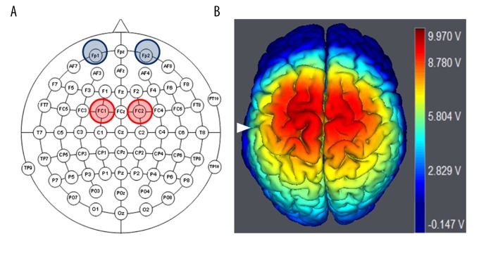
Figure 1.
Electrodes placement of bilateral anodal tDCS. (A) 10–10 EEG schematic view showing bilateral anodal tDCS electrodes placement, in which 2 anodal electrodes are placed over FC1 and FC2, and the cathode electrodes are placed over the left and right supraorbital area. (B) 3D brain image is structured by using software (Neuroelectric, NIC, Spain) to show the simulated electric field distribution in the bilateral DLPFC, supplementary motor, and M1 areas generated by the bilateral anodal tDCS stimulation, White triangle indicates central sulcus.

