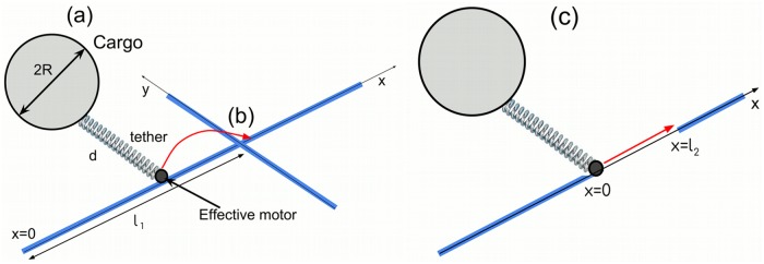
Fig 3. Schematic illustration of the set-up used in simulations.
(a) The cargo of radius R moves along the filament driven by the effective motor, which is attached to the cargo by the elastic tether of length d. The microtubule is oriented along the x-axis. (b) Another microtubule located at distance l1 from x = 0 and oriented along the y-axis perpendicular to the x-axis, blocking the movement of the cargo. (c) The motor-cargo complex located at the end of one filament (x = 0) is targeted to reach another filament at distance x = l2.

