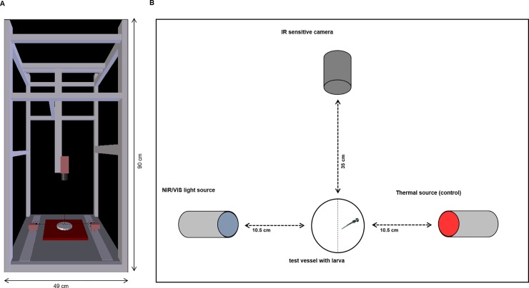
Fig 1. Scheme of the experimental set-up of the NIR light experiments.
(A) The custom-built computer vision system shows the position of the test vessel in the middle of the set-up, the camera above the test vessel and the position of the light sources. The computer vision system was totally covered so that no light from the surrounding area could enter the system. (B) A detailed view of the set-up: For each experiment, one larva was placed into the test vessel. The IR sensitive camera was set 35 cm above the vessel, and both light sources were 10.5 cm away from the test vessel. A thermal source opposite to the NIR/VIS light served as a control. We switched the position of light and thermal sources after each trial to exclude side biases. The vessel was divided into 2 halves with an imaginary line, one half illuminated by the light source (VIS/NIR), one half radiated by the thermal source (control side) (drawing of zebrafish larva by Kimmel et al. 1996 [12]).

