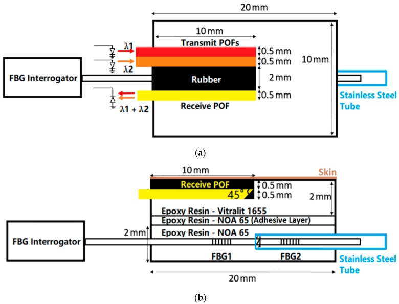
Figure 1.
(a) Plan view of the probe. Red and orange frames represent transmit POFs connected to two LEDs (660 nm and 850 nm). The yellow frame represents the receiver POF connected to the photo-diode. (b) Side view of the probe. The probe consists of two epoxy rectangular patches which are connected using epoxy resin. The top patch is the pulse oximeter whilst the bottom is the FBG pressure sensor. Two FBGs are fabricated in the core of the silica fibre which are connected to the FBG interrogator (see Section 2.2). The brown line represents the skin surface where the POFs are located.

