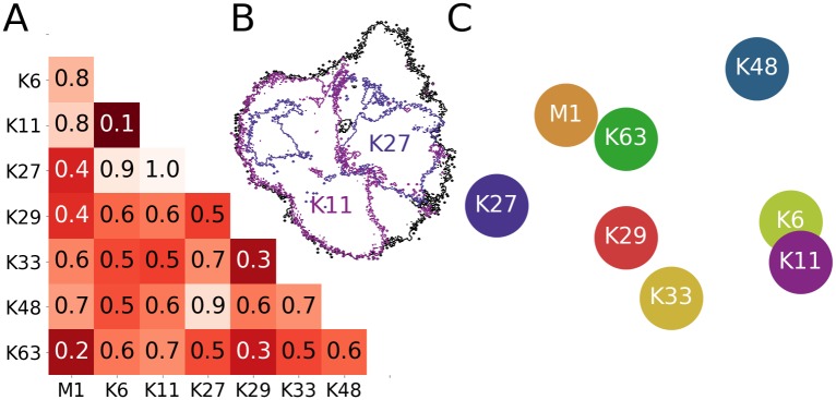
Fig 4. Comparison of 2D projections.
(A) Normalized earth mover distances (EMDs) between all projections in Fig 2 (i.e. all linker types). (B) Comparison of conformational landscapes to illustrate the EMD metric: all CG simulations (black); K11- and K27-linked diUb (pink and violet; EMD of 1.0). (C) 2D arrangement of linkage types based on their pairwise EMDs (i.e. according to (dis)similarity).

