Fig. 3.
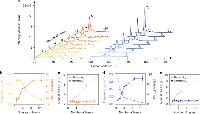
Layer number dependence of the zero-momentum magnon characteristics. a Raman spectra of the M1 (intensity multiplied by 20) and M2 magnons for 1–5 L, 9 L, and 13 L samples. Light yellow and blue shaded areas are the Lorentzian fits for the M1 and M2 magnon modes, respectively. The gray triangles highlight the satellite magnon peaks. b Frequency (ω0, left axis) and lifetime (Γ–1, right axis) of the M1 magnon as a function of layer number. c I. I. of the M1 magnon as a function of layer number with I. I. of the A1 phonon shown in gray for comparison. d, e Plots for M2 that are similar to b, c, with I. I. of the A3 phonon plotted in gray in e for comparison. Error bars in b–e represent the two SEs of fitting parameters in the Lorentzian fits to individual Raman spectra at different thicknesses

