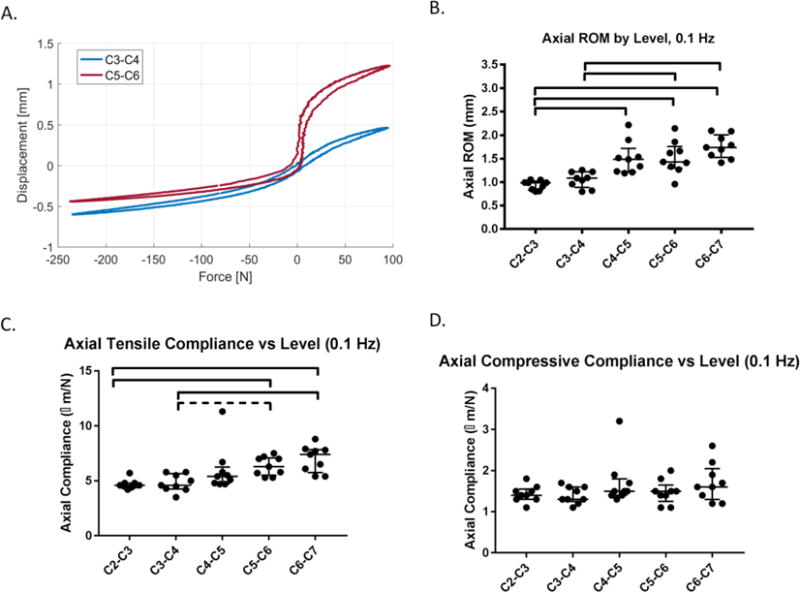
Figure 2. Biomechanical testing procedures and parameter definitions for torsional and axial biomechanical testing.

(A) The torque range was calculated as the peak to peak torque between ± 2° and ± 4°; the stiffness was slope of top 20% of the torque rotation curve at ± 2° and ± 4° which was averaged for clockwise and counter-clockwise stiffness values. (B) The range of motion was the total displacement between the common applied load for that frequency (for 0.1 Hz, 94 N and -227 N); the axial compliance was the slope of 20% of the displacement force curve.
