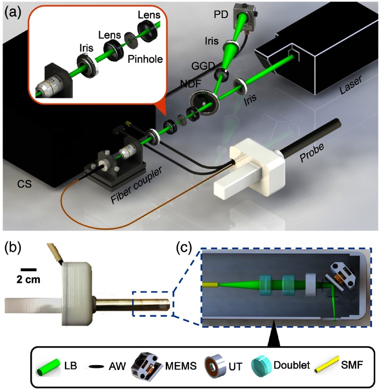
Fig. 1.
Schematic of the fsOR-PAE probe and its peripheral systems. (a) Setup of fsOR-PAE. CS, control system; GGD, ground glass diffuser; NDF, variable neutral density filter; PD, photodetector. (b) Photograph of the fsOR-PAE probe. A linear actuator in the white housing drives the azimuth scanning. (c) Schematic of the acoustic-optical coaxial confocal alignment in the probe. MEMS drives the scanning parallel to the cylindrical axis. AW, acoustic wave; LB, laser beam; MEMS, microelectromechanical system scanning mirror; SMF, single-mode fiber; UT, ultrasonic transducer.

