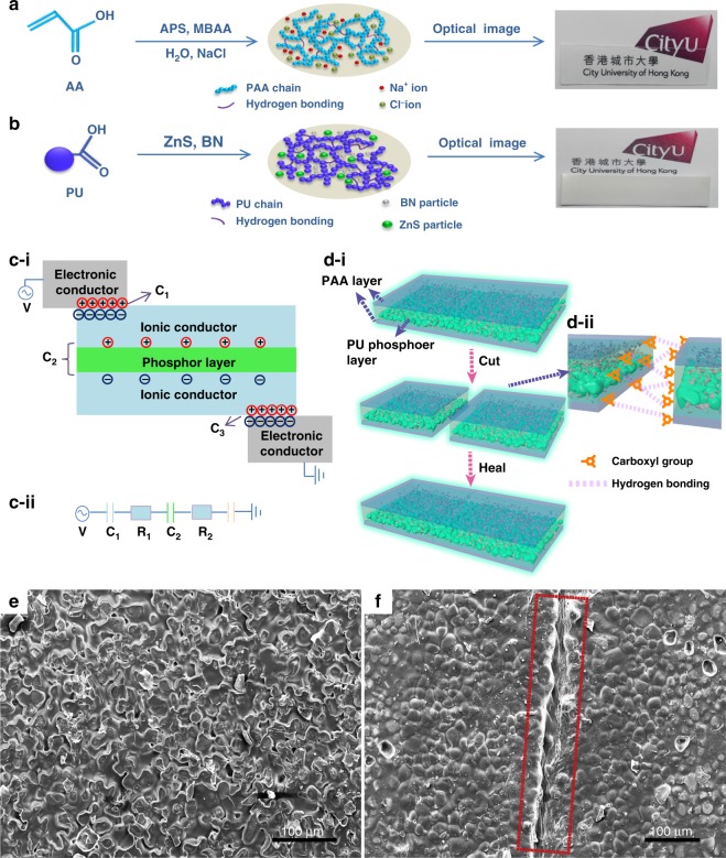
Fig. 1. Fabrication process and self-healing mechanism.
Synthesis process of the PAA/NaCl ionic conductor layer in (a) and the PU/ZnS/BN composite phosphor layer in (b), where the optical photographs of the as-obtained layers are shown. c-i Schematic principle and structure of the self-healable EL device. c-ii Equivalent circuit of an EL device, where C represents the corresponding capacitor and R represents the resistance of the ionic conductor. d-i Cutting–healing process of the as-fabricated self-healable EL device. d-ii Schematic of the cut region, which illustrates the self-healable mechanism and the configuration of each layer. e SEM image of the initial PU phosphor layer from bottom to top view angle. f SEM image of healed PU phosphor layer; the healed wound was represented by the red rectangle

