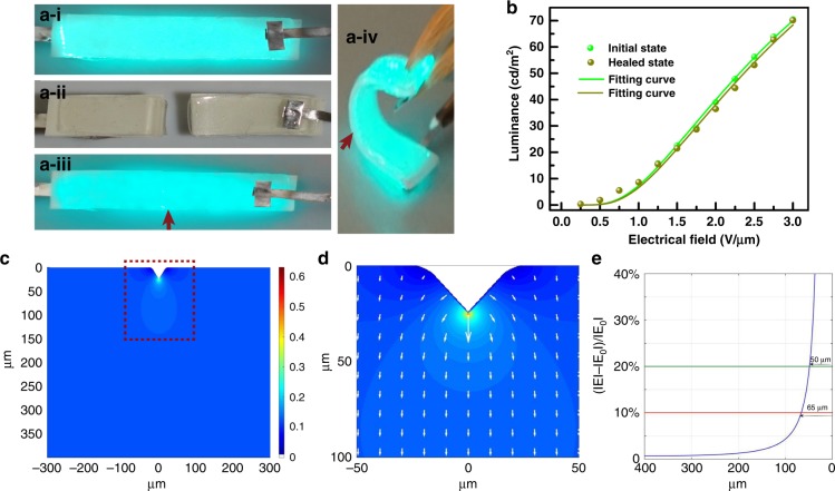
Fig. 3. Light-emitting performance of the self-healed EL device after cutting–healing process.
a Demonstration of cutting–healing process of the healable EL device. a-i–a-iii exhibit the initial working state, cut state, and revived working state, respectively, after healing. a-iv shows the bend working state of the healed EL device. b Luminance–voltage characteristics of the EL device for the initial and healed states. c Distribution of the electrical field across the phosphor layer, where the color bar represents the intensity of the electrical field. d Magnified image of a marked region in c, where the lengths and directions of the arrows represent the values and directions, respectively, of the electrical field adjacent to the healing region. e The value variation of the electrical fields as a function of the distance to the healing point, where ΙEΙ represents the values of the redistributed electrical fields and ΙE0Ι represents the original value of the distributed electrical fields before the cutting–healing process

